The Solar Magnetograph of the Ondrejov Observatory
Photoelectric magnetograph of the Ondrejov observatory has been put into the operation in 1990.
The instrument working as a Stokesmeter measures the
longitudinal components of the magnetic and velocity fields
and intensities in selected parts of a spectral line
profile. We present the method of measurement, calibration,
primary data processing, their storage, as well as storage
of the final results.
1. Description of the instrument
1.1 Feeding telescope and spectrograph
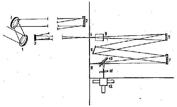
Our photoelectric magnetograph is placed in a spectrograph fed by a horizontal telescope equipped with a Jensch's type coelostat having the diameters of both of its mirrors 600 mm (See Fig.1). The diameter of the main telescope mirror has 500 mm and its focal length is 35 m. The spectrograph of the type Cerny-Turner uses the Bausch & Lomb grating with 632 grooves/mm. The focal length of both collimator and camera mirrors is 10 m and their diameters are 230 mm and 370 mm respectively. The telescope as well as the spectrograph have been manufactured by C. Zeiss, Jena on the base of our specification (Ambroz et al., 1980). It is supplied by a system of coordinates and by a guiding and scanning automat which enables to scan any rectangular area on the solar disk.
1.2 The principle of the magnetograph
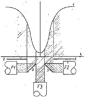
The magnetograph measures the Stokes parameters V and I in both wings of a spectral line (Fig.2). With the aid of a compensator of Doppler's line shift (11/Fig.1) is the spectral line kept in a symmetrical position against the block of slits with photomultipliers (Fig.2), registering signals from both line wings and from the center of the line profile. In dependence upon the polarization of individual parts of the spectral line profile the intensity of light is modulated by a photoelectric modulator (9/Fig.1) with a code-impulsive modulation.

Fig. 1: Main optical elements of the Magnetograph II: 1 - Jensch's coelostat; 2 - telescope main mirror; 3 - plane mirror; 4 - entrance slit; 5 - collimator; 6 - difraction grating; 7 - camera mirror; 8 - focus plane; 9 - photoelectric modulator; 10 - diagonal mirror; 11 - compensator of the Doppler's line shift; 12 - block of the slits with photomultipliers

Block of the slits with photomultipliers (for the line 5253,47 A): 1 - intensity of the spectral line profil; 2 - first slit (24nm); 3 - second slit (8nm); F1,F2,F3 - photomultipliers
1.3 Image sampling
The selected rectangular area is scanned by a velocity of SV = 60"/sec in lines in which the sampling is made in the direction E-W. Analog signal of each of the eight measured channels is digitized into eight bits. The sampling density is steady, making 0.1" during the solar image shift across the entrance slit of the spectrograph in the direction of the measured line.
The width of one pixel is defined by the degree of numerical integration N, given by the number of summarized digital samples. The height of the pixel is in a standard scanning regime 1.5 times greater than the width and it is given by the distance of two subsequent scanning lines P. Each sample obtained in this way is stored in two bytes form in the main memory of the computer. Standard regimes of registration differ by the degree of numerical integration. They are as follows: the regime of fine scanning (N = 16), normal regime (N = 32) and regime of fast scanning (N = 64). In a special regime the parameters SV, N and P are eligible.
1.4 The output of measured quantities
channel 1 - parameter V in the blue wing of the spectral line
channel 2 - parameter V in the red wing of the spectral line
channel 3 - parameter I in the red wing of the spectral line
channel 4 - parameter I in the blue wing of the spectral line
channel 5 - intensity of the light in continuum
channel 6 - intensity of the light in the center of the Sun
channel 7 - intensity of the light in the center of the line
channel 8 - the Doppler velocity
1.5 The main parameters of the magnetograph
1.5.1 Space and time resolution
| Regime | Pixel width | Pixel height | Degree of integration N | Duration of measur. area: 300''x200'' |
|---|
| fine | 1,6" | 2,4" | 16 | 15 min 12 sec |
| normal | 3,2" | 4,8" | 32 | 7 min 40 sec |
| fast | 6,4" | 9,6" | 64 | 3 min 54 sec |
| special | all parameters are eligible |
1.5.2 Minimal sensitivity in standard regimes:
- Longitudinal component of magnetic field
- about 10 - 20 Gs
- Doppler velocity
- about 20 m/sec
- contrast of intensities
- about 1 %
It is possible to increase the sensitivity by using special
regimes.
2. The course of the measurement
At the beginning of the measurement we calibrate the magnetograph registering the dark current and the light intensity coming through the device enabling us to estimate the degree of circular polarization. In form of a complement to the observing protocol we select the parameters of measurement. The process of measurement of the chosen solar region is then operated by a computer. In a real time we see on a display the maps of Stokes parameter V and the Doppler velocity. Using these maps we may select optimal parameters for the next measurement.
3. Processing of the primary data files
After each measurement of the selected area we have eight data files registered on a floppy disk. Each file contains data of one of the measured analog channels. The length of the file is changeable and it depends on the size of the measured area. Except of the eight data files each measurement contains still the file of constants and the file of the protocol of measurement. Both these files have a steady length of 1000 and 3990 bytes.
The separation of measured physical quantities into individual files is suitable due to the easier distribution of data among the working areas of the computer and due to the faster access to them.

